CASE STUDIES
Case Study #1
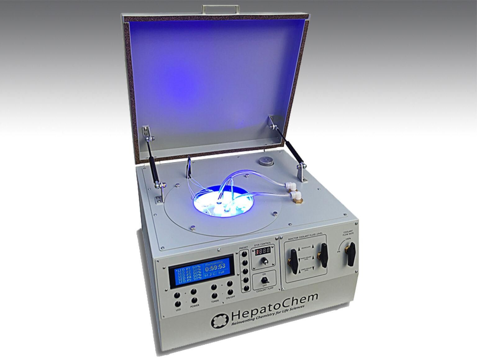
Case Study: Photoreactor Controller
Overview of Collaboration
The partnership with this client began as a proof-of-concept to develop a multi-channel, high-power, variable-intensity ultraviolet (UV) LED control system. Initially designed to explore the feasibility of precise UV light control for laboratory use, the concept quickly evolved into a sophisticated, first-of-its-kind photoreactor tailored for cutting-edge chemistry labs. Today, these systems are deployed in leading laboratories worldwide, enabling groundbreaking research in photochemistry, catalysis, and material science.
Engineering Contributions by Savoy Engineering, LLC
Savoy Engineering, LLC has played the central role in the development of the photoreactor by designing all the controller electronics and writing the embedded software that drives the system’s functionality. The design process required close collaboration with the client to ensure the system met stringent performance, reliability, and safety standards.
Key aspects of the project included:
- Hardware Development:
The electronics were designed using Eagle CAD, where custom schematics and multi-layer PCB layouts were carefully designed to handle the complex requirements of high-power UV LED control. Components were selected to balance cost and performance. A header where small custom PCBs can be attached was provided to allow for the addition of future features and functions without requiring a new board design. All hardware design files are maintained in a secure, version-controlled Git repository to ensure traceability and facilitate ongoing development.
- Firmware Development:
The embedded software, written in C++, was designed to provide real-time control over LED intensity, sequencing, and system diagnostics. Advanced algorithms ensure precise synchronization of multiple channels, allowing users to fine-tune the UV output for specific needs. The firmware is modular and scalable, enabling rapid integration of new features or enhancements as research demands evolve.
Seamless Firmware Upgrades
To ensure the client’s customers always have access to the latest innovations, end-users can easily upgrade their systems through a user-friendly interface, ensuring their equipment remains state-of-the-art. Firmware updates are delivered securely via the client’s distribution channels, with each version rigorously tested to maintain reliability.
Innovation and Impact
This photoreactor has set a new standard in the field, offering researchers unparalleled control over UV light parameters. Its deployment in laboratories across the globe underscores its impact on advancing scientific discovery. By transforming a conceptual prototype into a widely adopted commercial product, Savoy Engineering has demonstrated its commitment to delivering innovative, high-quality engineering solutions.
Ongoing Collaboration
Savoy Engineering continues to work closely with the client to enhance system capabilities, including developing next-generation control algorithms, expanding the range of supported experiments, and integrating IoT features for remote monitoring and data analysis. This ongoing collaboration ensures the photoreactor remains a cutting-edge tool for scientific exploration.
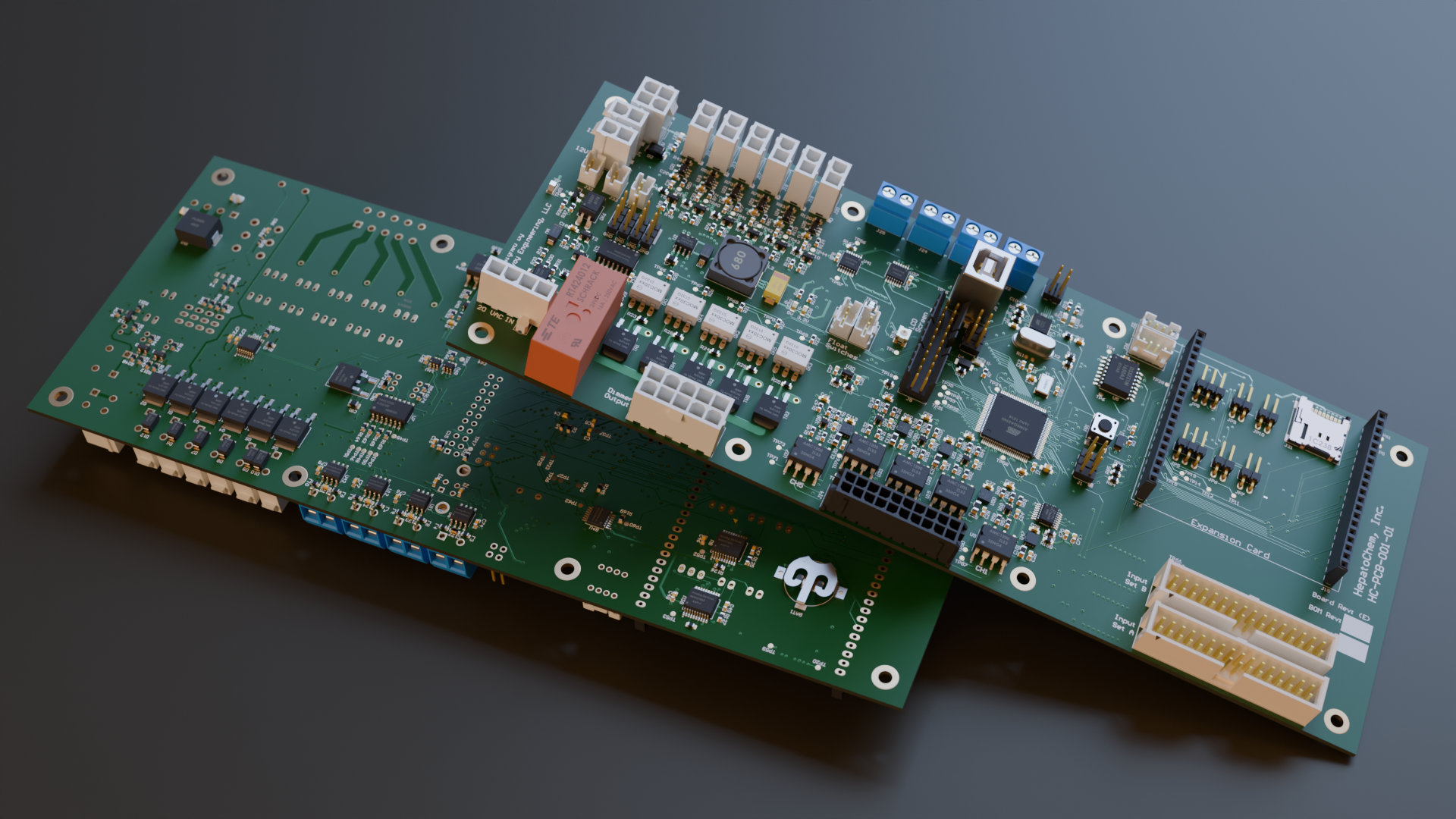
The electronics include:
- 240x64 Graphical LCD screen, and user interface buttons
- ATMEGA2560 MCU
- 5x forward phase cut AC chopper circuits
- Flexible multi-input AC safety cut-off circuit
- 6x 12V switched circuits for controlling pumps and valves with current monitoring
- Isolation amplifiers monitor the current and voltage driving the LEDs
- 16x channels of 12-bit ADCs monitoring critical currents and voltages
- 4x Type-K thermocouple channels
- 2x RTD temp probe channels
- microSD card for data logging
The software includes:
- Graphical LCD control
- Multi-screen user interface
- LED calibration routine
- Real Time display of critical system parameters
- Software versioned and managed in git repository
Case Study #2
Case Study: Borehole Geophone System
Overview of Collaboration
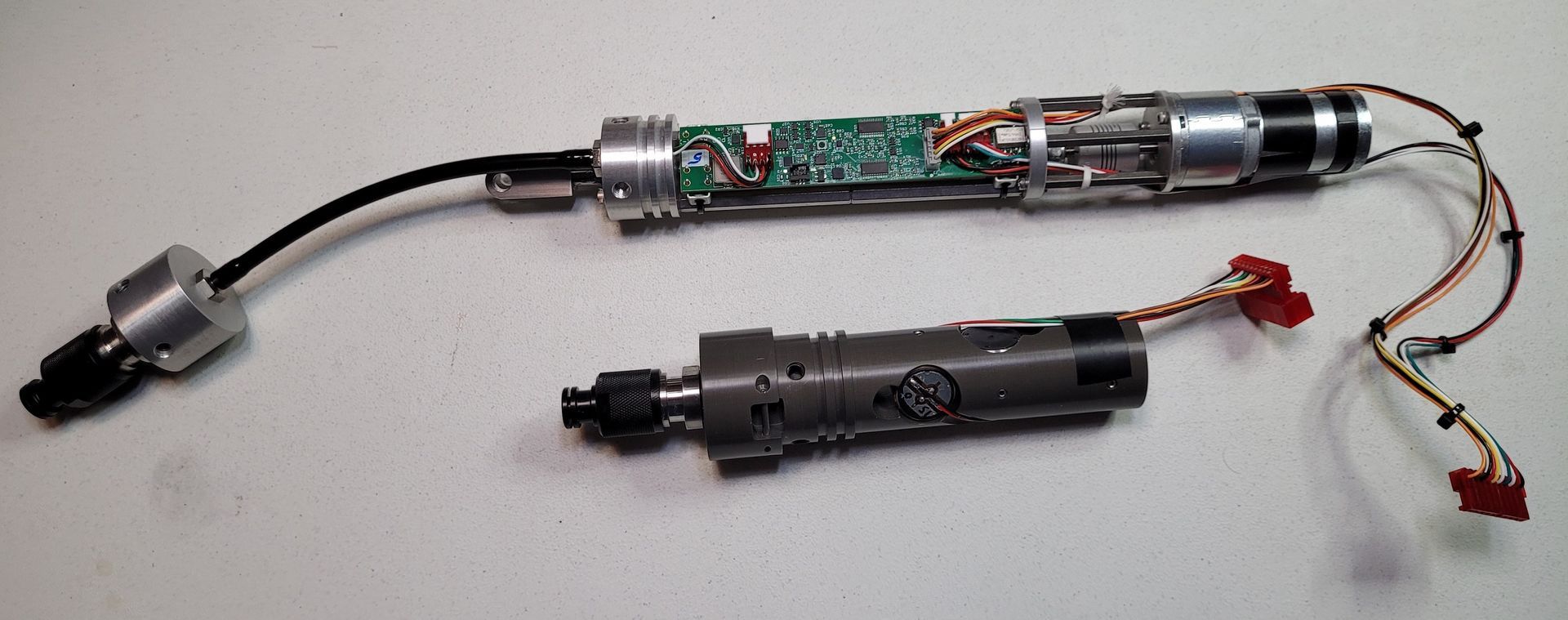
This client needed a design for their next generation borehole geophone system. Borehole geophones are seismic instruments (long and cylindrical in shape) that are lowered into a borehole in the ground. These boreholes may be several hundred meters deep and may extend below the local water table. Multiple geophones can be connected with cable segments to form a linear array. An external energy source (such as a sledge hammer, or hydraulic hammer) is used to create a shockwave through the ground that is recorded by the geophones.
The relative time-of-arrival, frequency, and amplitude of the shockwave received by various geophone tools in the array contains lots of information about the makeup of the ground being studied. The captured data is stored in an industry standard format and used to obtain information about geological structures and characteristics or the surrounding terrain. This information is of critical importance to many industries including construction, and oil and gas, to name a few.
The client has deep experience, and a long track record, in this industry and needed this particular system to support up to 24 geophones in an array, and be managed by a controller on the surface. This controller is connected by USB to a computer running the client’s custom software suite. Each geophone was to be equipped with three-axis high-resolution accelerometers. A magnetometer in each geophone is used to align the data of all individual geophones in the array.
The system has user configurable sample rates, resolution, collection duration, and other parameters. The geophones are firmly mechanically clamped against the borehole walls to ensure a good coupling through which the vibration energy could be measured. Furthermore, the client needed multiple linear arrays to be connected together to form a 2D array across multiple boreholes.
The diagram below depicts the system and its various components:
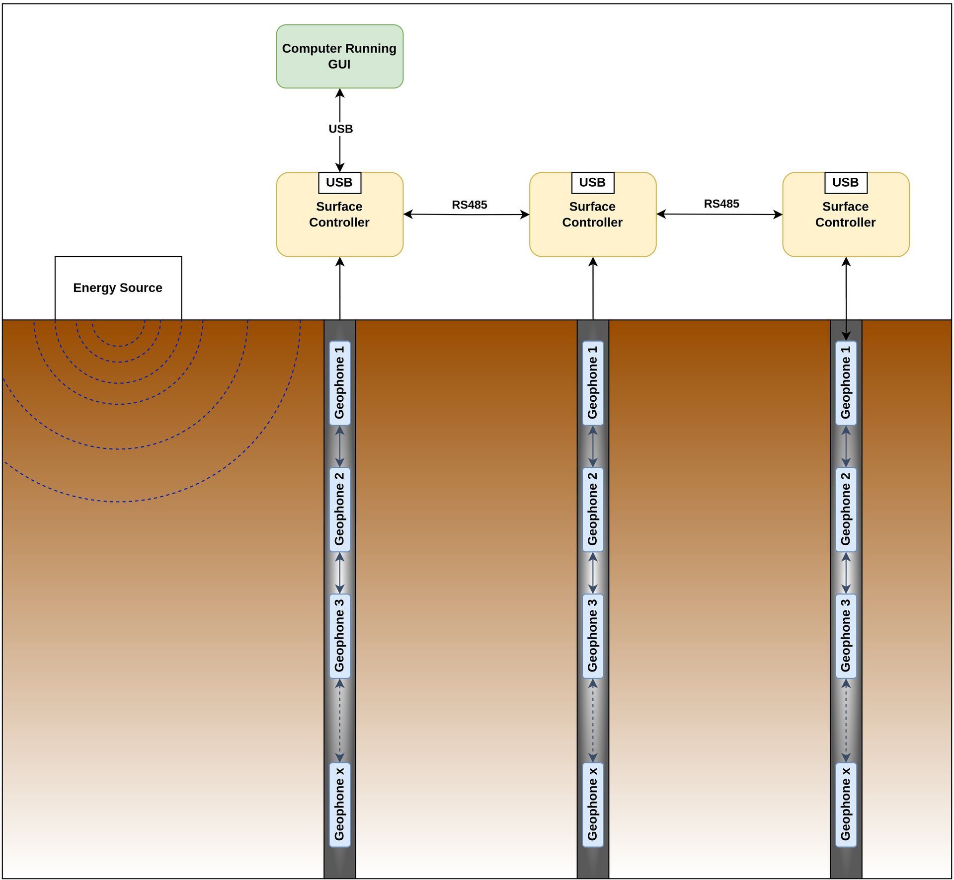
The system consisted of two custom PCBs, the “Surface Controller”, and the “Geophone”, which were both created in Eagle CAD (now Fusion 360). Both boards used the same STM32 MCUs with custom FW. The hardware design files, and FW source code was all versioned and maintained in with Git.
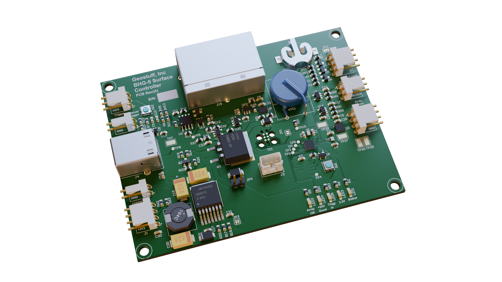
- Surface Controller
- Hardware Development:
The Surface Controller hardware needed to manage the power delivered to the array, connect to the array over RS-485, and to a computer over USB. An external trigger input is used to precisely time-align the data collection of the array. The design included various user switches and a status LED. The user interface was mostly handled by the GUI that ran on the connected computer. A MicroSD card provided storage to store captured data, or other information. Additionally, two RJ-45 jacks provided the ability to connect multiple Surface Controllers together so they could operate in unison. Multiple controllers allow for the creation of a 2-dimensional array and more comprehensive data collection.
- Firmware Development
The firmware was written in C for an STM32L4 series MCU. The primary job of the FW was to execute the requests from the GUI (received over the USB connection), and manage the array responses. The MCU/FW translated these high-level requests to the low-level operations to control the array. A messaging system was implemented that allowed the GUI to communicate, and receive captured data from all the controllers connected by the full-duplex RS-485 link. FW on the Surface Controller is updatable over the USB port.
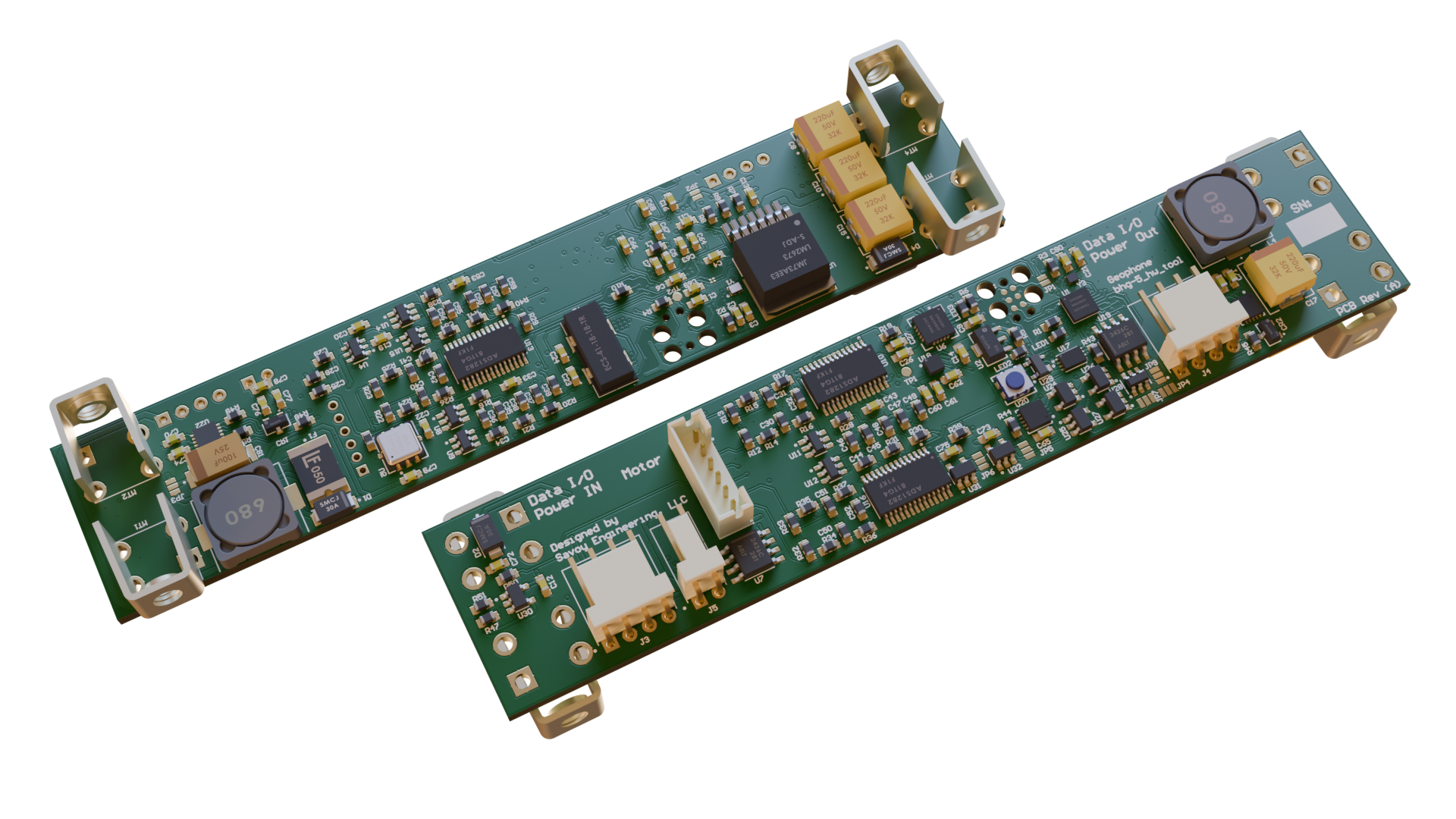
- Geophone
- Hardware Development
The hardware for the geophones themselves had to meet space and power limitations imposed by the application. These PCBs were long and narrow in-order to fit into the cylindrical housing. Connectors were chosen so that the assembled system with wiring connected would fit. The design needed to interface with the three highly sensitive geophone sensor elements with 32-bit Delta-Sigma ADCs. A brushed DC motor controller with current sensing operated the clamps that held the instrument rigidly in place in the borehole. The design also included the previously mentioned magnetometer, several MBs of external SDRAM which can be used for extended data collection. A FLASH memory chip is included for the storage of calibration values, important system states, and firmware updates.
- Firmware Development
The primary function of the geophone FW was to capture 3-axis data from the accelerometers with precise timing (synchronized with the rest of the array), store data once a trigger signal was received, and return the data to the Surface Controller when requested. The RS-485 communications interface provided the ability to communicate with the array of geophones.
The analog to digital converters had a complex suite of features that needed to be configured and that might be adjusted based on the needs of the operator. A circular buffer was used to store the captured data. The external SDRAM was not needed for the initial delivery but was included in the design with the expectation of new features in the future. The motor control operation was designed to clamp the instrument in the borehole for data capture, and release the clamp when it was time to remove or reposition the instrument. The motor operation was controlled using current measurements. The magnetometer interface was implemented with the ability to calibrate the system to correct for hard-iron offsets introduced by the housing.
Below is a screen shot from the GUI (not developed or written by Savoy Engineering) showing data captured from an array of two geophones
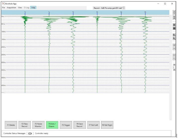
The resulting system is modular and expandable and consists of a Surface Controller that connects to a computer running special analysis software (written by a third party), and up to 24 borehole geophones in a linear array. Multiple arrays can be linked together to provide additional information to the operators.
Development on this system continues as new features and behaviors are needed.